The conservative, adhesive treatment of teeth in complex, endodontic situations. Case histories from practitioners for practitioners.
In 1994, after three years as an assistant, Dr Wolfgang Gänsler founded his own general dental practice in southern Germany. He was originally motivated to begin a career as a restorative general dentist after attending a course run by Professor Alexander Gutowski in the same year. This was followed by other training courses in all specialist areas of restorative dentistry.
Since 1997, Dr Gänsler has cared for his patients with a qualitative and holistic approach to the complex areas of endodontics, surgery, implant and restorative and conservative dentistry. He was one of the first German dentists to use a microscope in his work.
Alongside his career in general dentistry, Dr Gänsler continues to teach at advanced training events, sharing his quality-oriented practice philosophy in areas such as dental dams, digital photography, adhesive technology, endodontics with OPMI, functional analysis, complete centric reconstruction and a marketing and accounting course (Let‘s Talk About Money). Dr Gänsler is a member of the European Association of Dental Implantologists (BdiZ) and the German Association for Aesthetic Dentistry (DGÄZ). He publishes practice-oriented articles on the topic of restorative dentistry in national and international specialist journals.
Introduction
Since the 1990s, there have been significant changes in the restorative treatment of damaged teeth. Both adhesive technology and endodontics have seen great leaps in development. Today there are proven treatment concepts for established practitioners, enabling a high percentage of teeth
to be retained.
Using the following practical descriptions from daily practice, complete with case histories, I would like to demonstrate the potential, the opportunities and the technical procedures, which enable even massively damaged teeth to be reliably and permanently restored using adhesive technology and endodontics in everyday clinical practice.
Clinical case one: female patient with initial endodontic treatment and extensive decay in tooth UR6
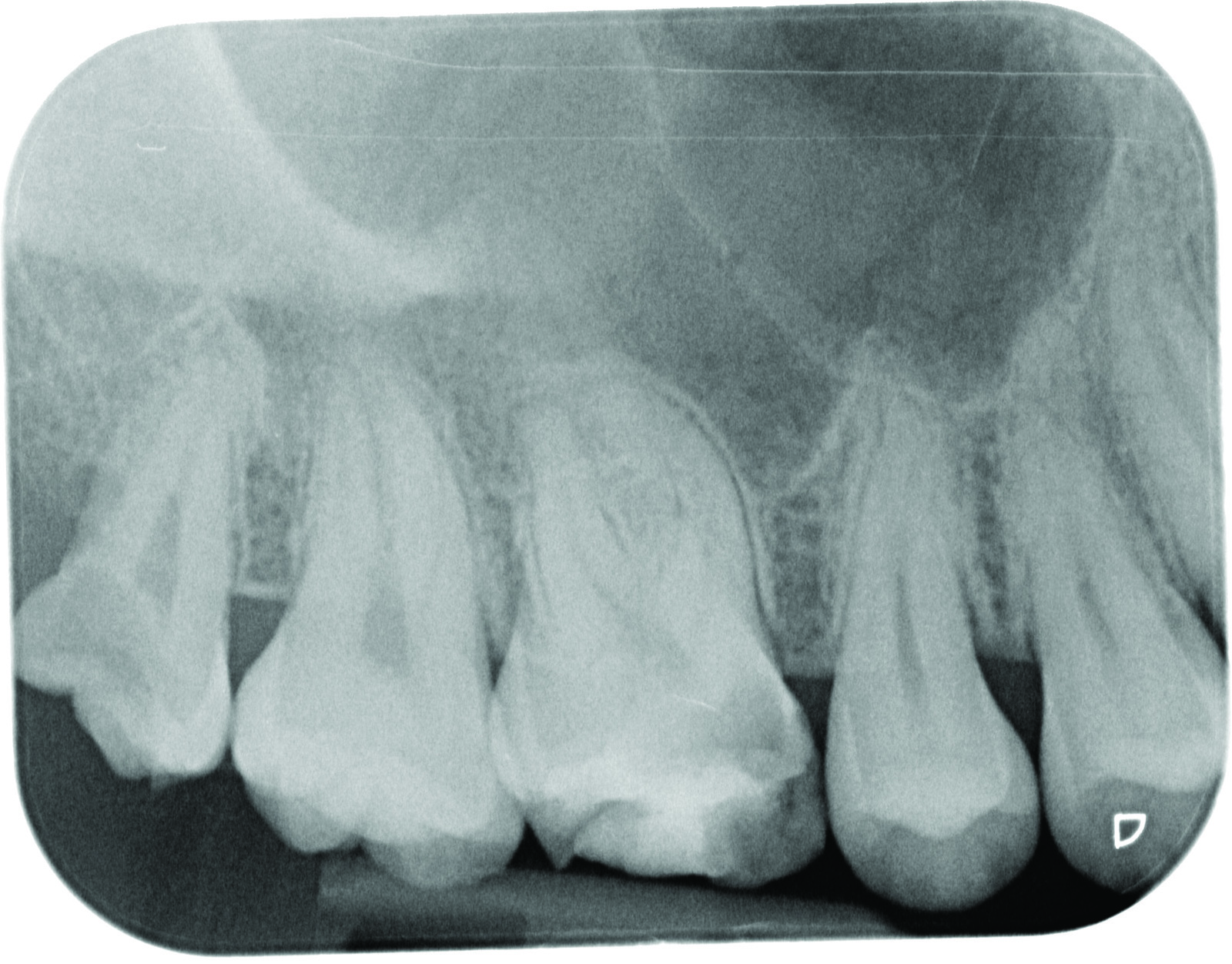
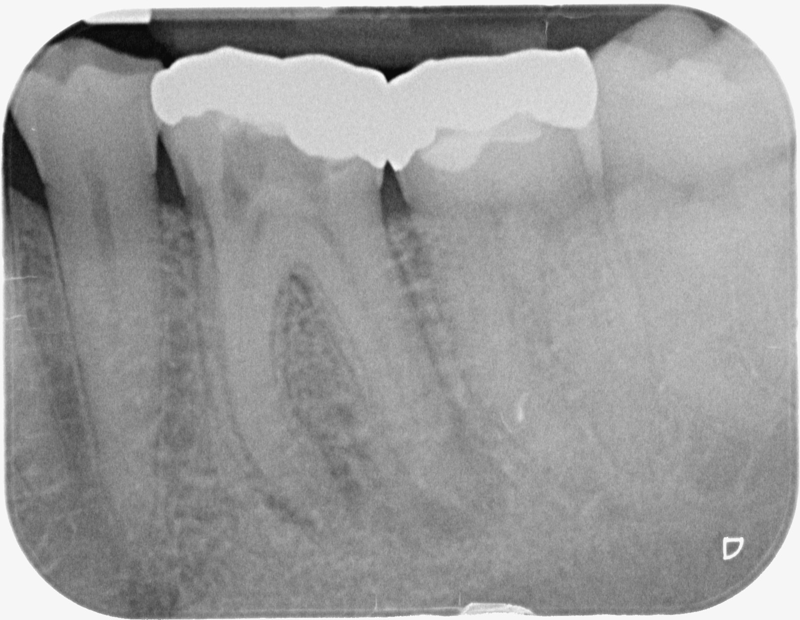
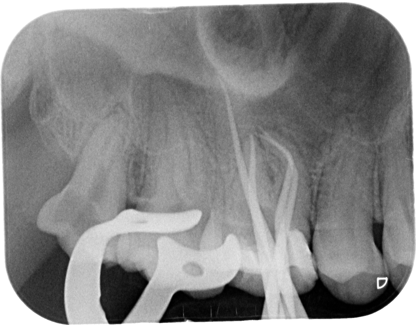
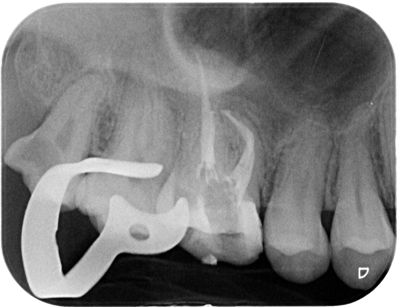
On 20 March 2017, the patient presented in the practice with severe pain in tooth UR6. As this was an emergency appointment, X-rays were taken (Figure 1), followed by a vitality test with COM2 rods (-78 degrees) and a positive percussion test. A diagnosis of ‘extensive decay through to the pulp chamber and suspected acute pulpitis’ and possible procedures were discussed with the patient.
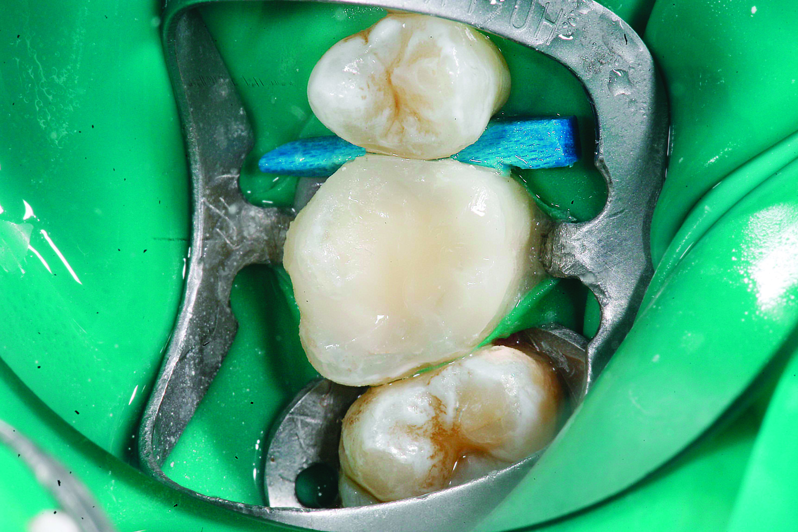
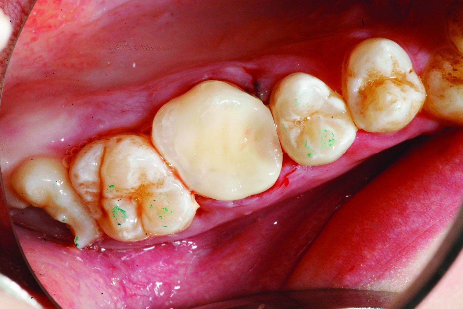
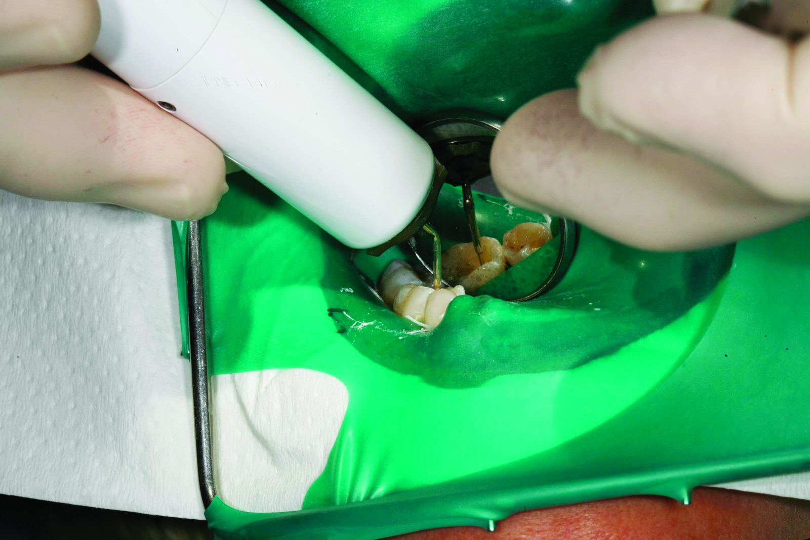
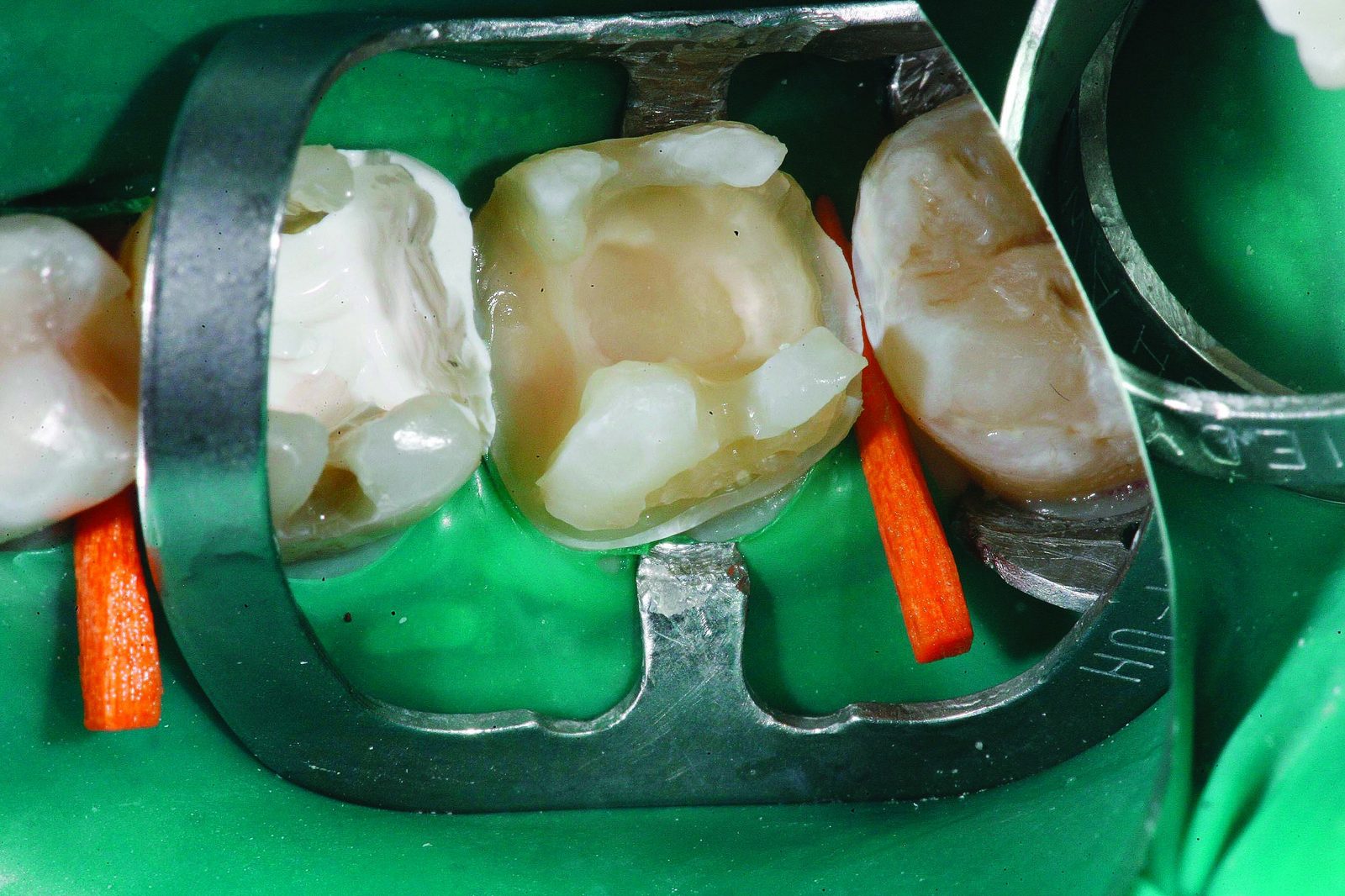
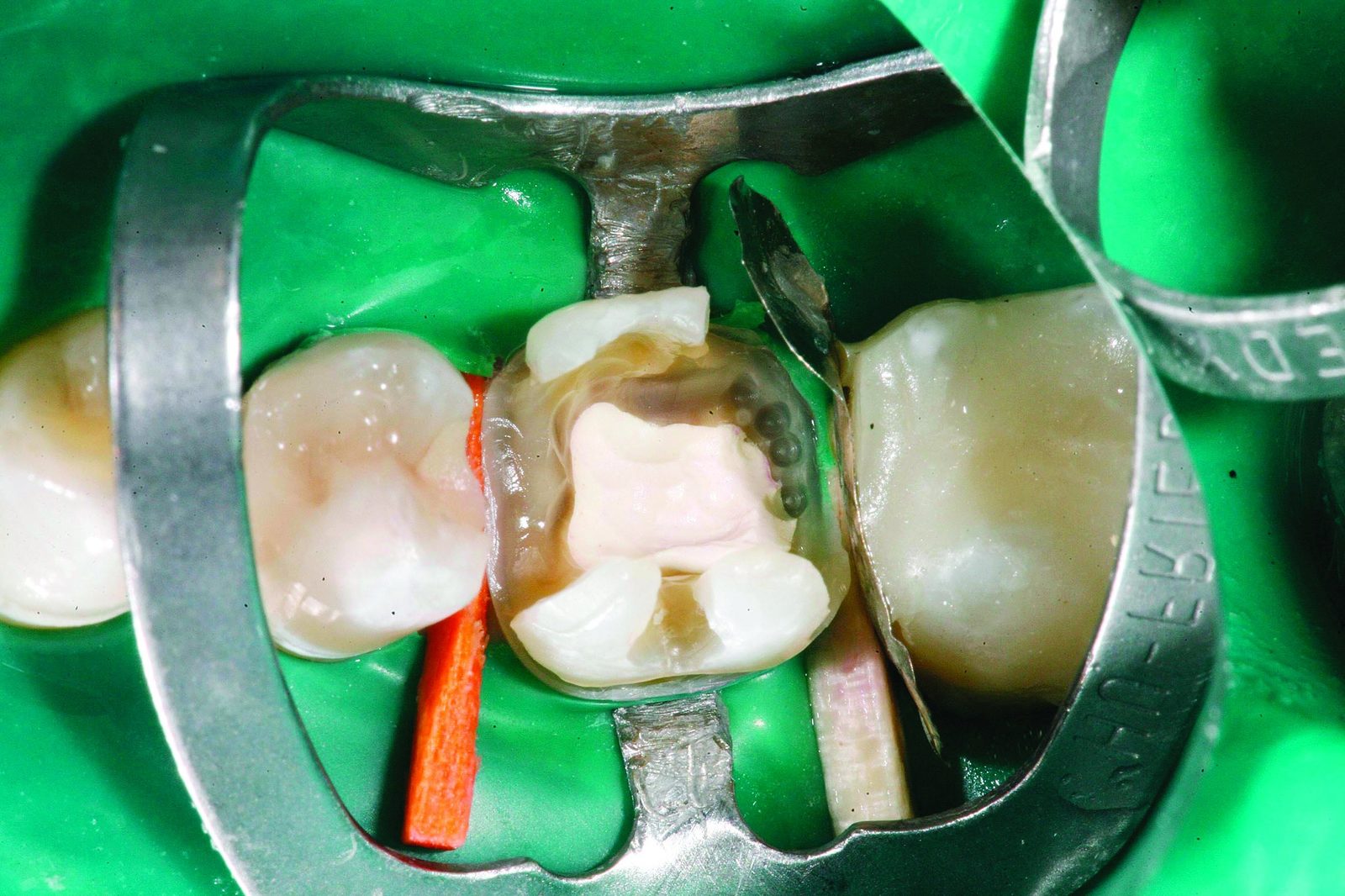
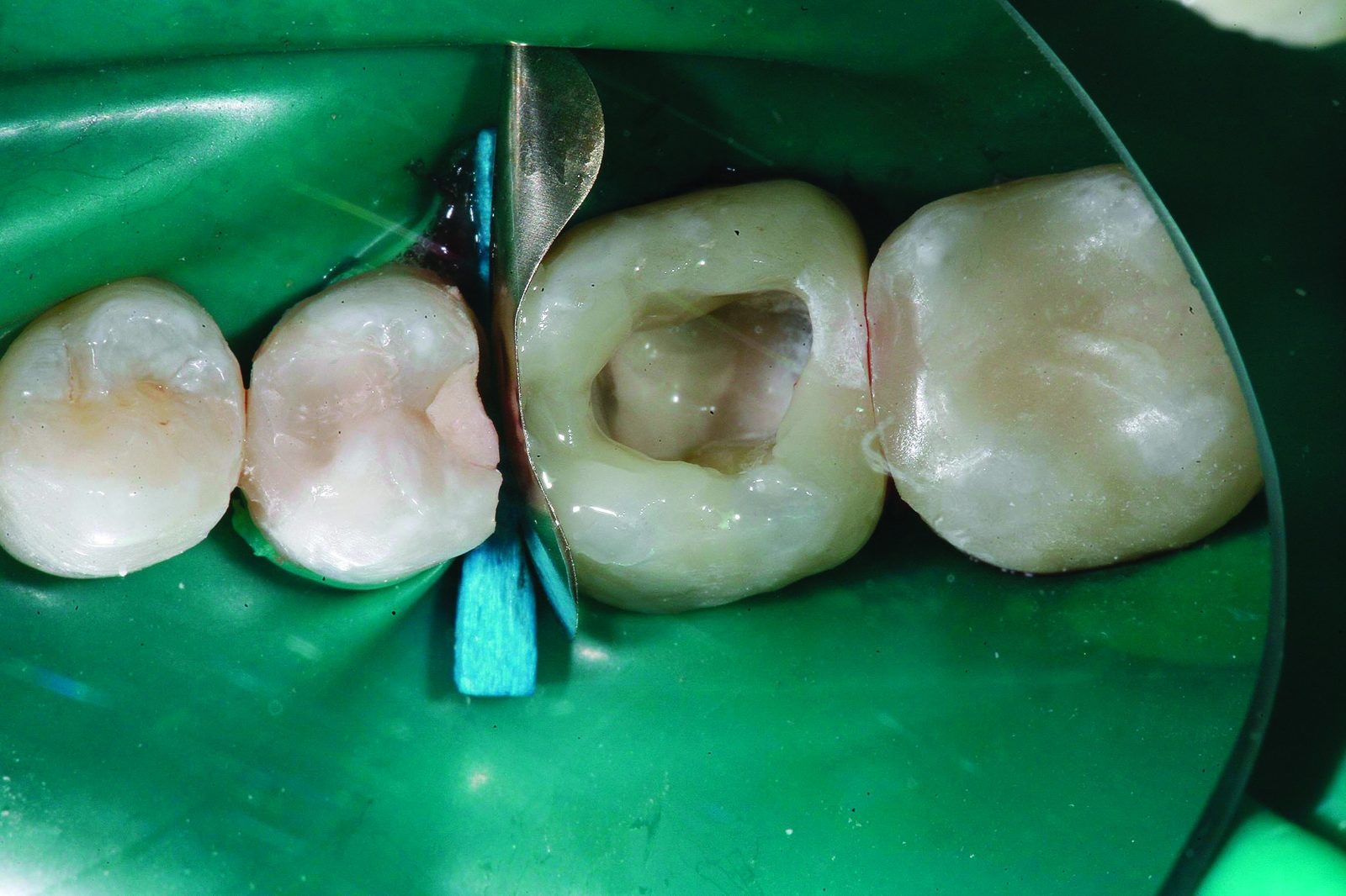
In the emergency appointment, following palatal infiltration and conductive anaesthesia (for the subsequent placement of a snug-fitting rubber dam clamp on tooth UR7), complete drying of the tooth is effected using a dental dam (extra heavy). To protect the anterior tooth UR5, a thick diamond-coated steel strip is clamped between the teeth to beneath the level of damage in tooth UR6 (Figure 2). Along this steel band, to the level of the healthy root dentine, decay-free excavation can take place without damaging the dental dam or the neighbouring tooth (Figure 3).

Because of the narrow time-frame and the emergency situation, the tooth is trepanned during the same appointment almost as a ‘compromise’, the pulp chamber roof is completely removed, the pulp chamber opened and sufficient access is ensured to the four canals.
The first part of the treatment — ie anaesthetic and drying, the removal of the previous restoration, trepanning and opening of the pulp chamber — takes place with the use of dental magnifying glasses offering 4.3x magnification.
The second part then takes place under the optimum, perfectly lit dental microscope: the endodontic treatment, inspecting and enlarging the root canal entries, the initial manual instrumentation and mechanical preparation. To complete the first treatment session and following successful manual preparation through to apical preparation extent ISO 25 and sufficient chemo-mechanical disinfection with 5% sodium hypochlorite, a medicated insert with calcium hydroxide (Apexit) is applied to the four dry canals. Subsequently, the tooth – because of the exceptional time situation – was sealed provisionally with a composite build-up of Harvard cement. The actual mechanical instrumentation was planned for the next appointment. Once the patient’s pain was relieved, a second treatment with a duration of two hours was booked for 29 June 2017. In this appointment, once the decay was completely removed using a decay detector and magnification, the tooth was built up with a coated and multi-layered synthetic restoration affixed with adhesive.

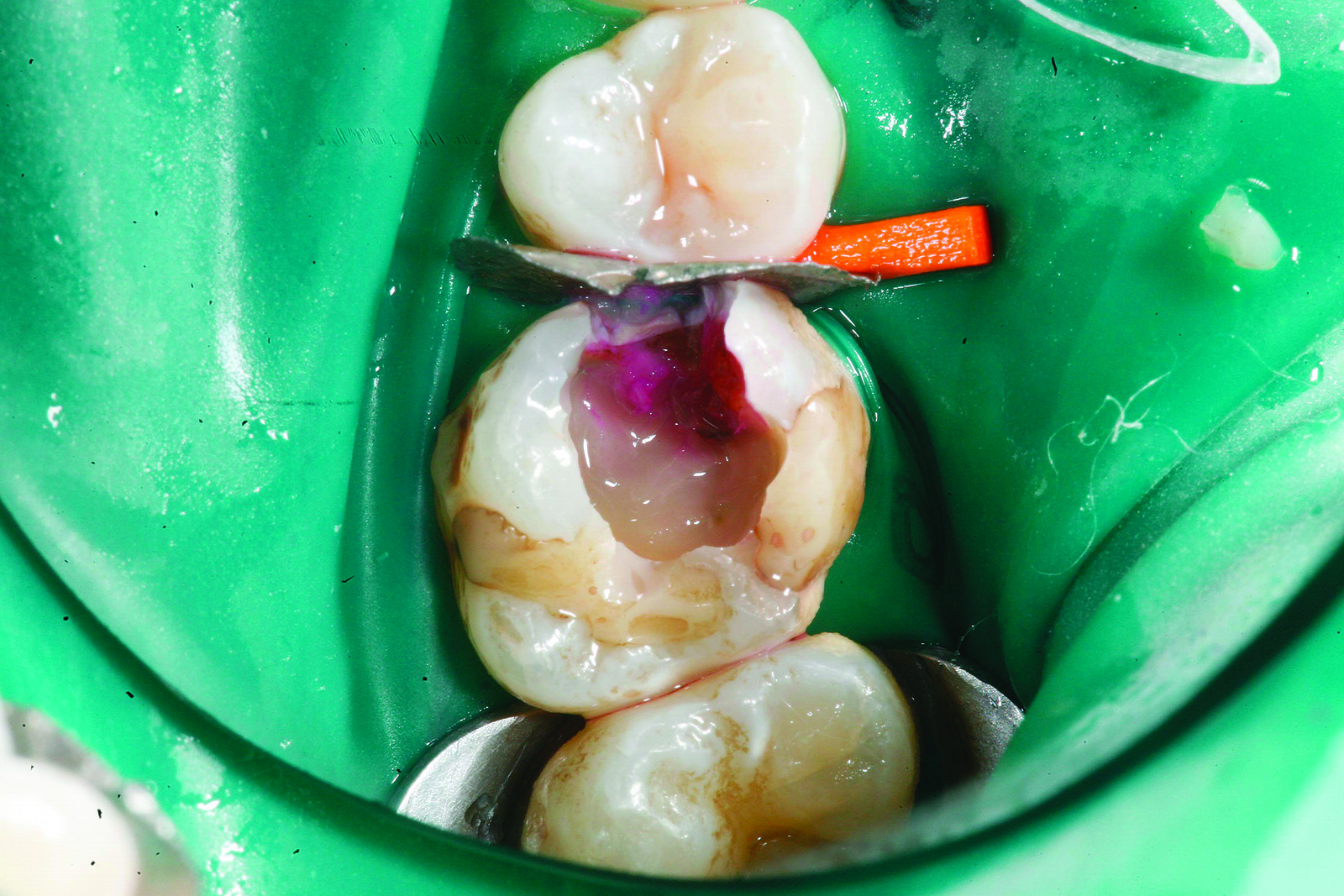
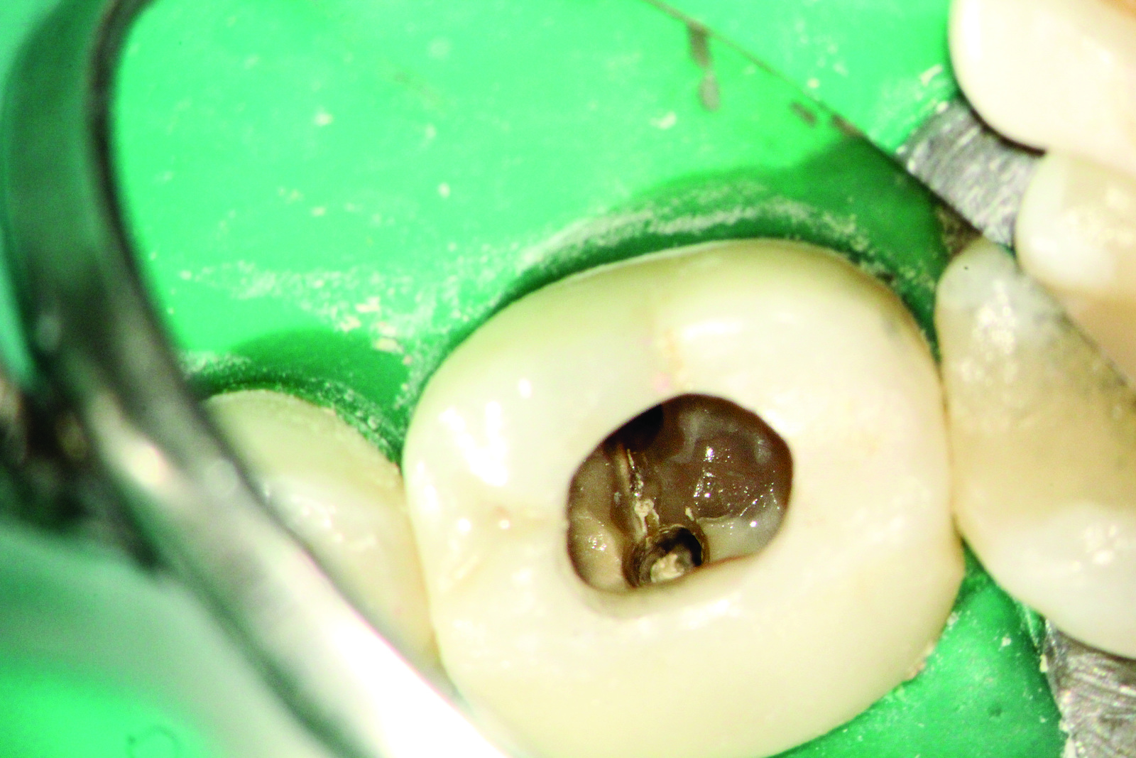
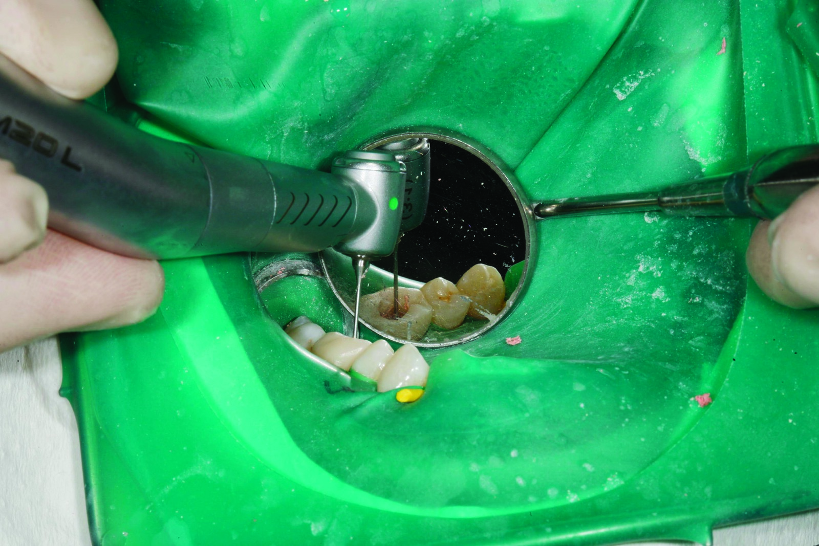
The subgingival, close-lying metal strip with the diamond-coated side to the tooth undergoing treatment is also ideal for adhesive composite build-up, as it serves as a ‘matrix’ in the lower new cavity section (Figure 4). Figure 4 shows the removal of the previous restoration with a sharp crown slitter in the Kavo Turbine Mastertorque M9000L. As the dental dam kept slipping upwards laterally, it had also to be fixed down. Due to cervical decalcification, which can be widespread, with transition to a softened condition, a butterfly clamp is used for the dental dam, which is fixed gingivally as a ‘retaining clamp’ centrally on the number 6 (Figure 5).
In the second appointment, all decayed areas as well as the entire previous, insufficient filling were removed right to the decay-free dentine/enamel (Figure 5). On the canals prepared on 20 June, the provisional cover with canals covered by the medicated insert can still be seen and this is removed during this treatment session for the final root canal preparation. After complete removal of the previous restoration and the decay by repeated dying with a decay detector – in addition to adhesive anchoring using bonding system Optibond XTR (made by Kerr) – a small, sharp bud burr is used to drill macro-mechanical retention pits in the mesial and palatal ledges (Figure 6).

Because little substance of tooth UR6 remained, build-up was effected initially using a composite. In the lower layers, a flowable composite (eg Herculite XRV made by Kerr) and in the coronal sections, a nanohybrid composite (eg Harmonize made by Kerr) was used. If we had now carried out the endodontic treatment – with the cavity open in all directions – with a sodium hypochlorite solution constantly applied to the pulp chamber, there would have been the risk that the disinfection solution would flow out of the tooth into the dental dam setting. To ensure that continuous rinsing throughout the subsequent chemo-mechanical expansion of the canals could be effected using a localised and continuously replaced sodium hypochlorite solution, I began as usual to build up the tooth adhesively in layers.

To do this, I sprayed a first layer of flowable composite (eg Herculite XRV made by Kerr) onto the macro-mechanical retention pits, which then flowed very well along the steel matrix.
The layers were built up portion by portion and were then coated and shaped with a hybrid composite such as Harmonize made by Kerr so that an absolutely gap-free finish was ensured.
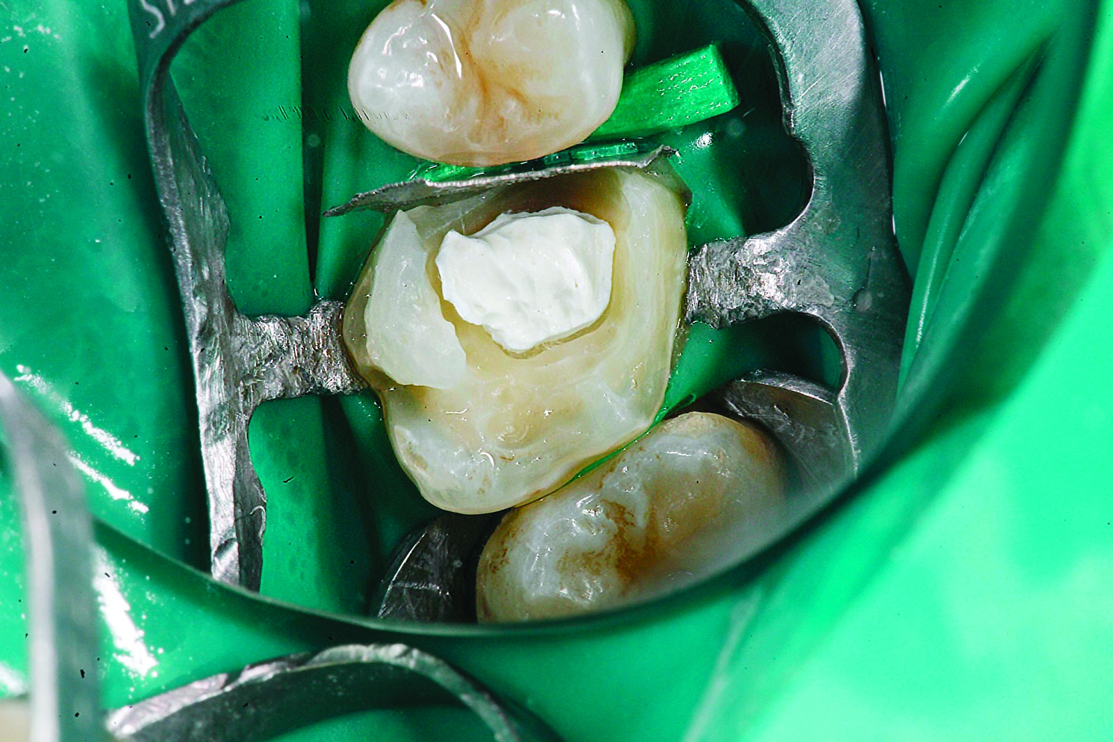
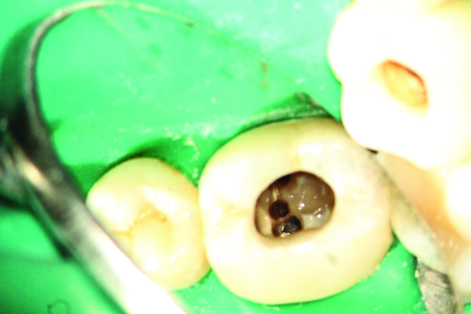
Suitable modelling instruments here are the Comporoller (made by Kerr) and a Davinci brush size one lightly moistened with bonding agent, which is used as the final modelling instrument for optimum border moulding. When the entire circular composite build-up is completely coated, there is a small ‘pool for the NaOCl solution’ in the middle as an access opening (Figure 7). In Figure 7, the opened canal access cavities in the pulp chamber floor area are just about visible.

In this second treatment session, the canal entries are sought, the conical, funnel-shaped access cavities are expanded and established in the canals, manual pre-instrumentation to the apex of the constriction and mechanical expansion to a preparation extent took place. This latter enabled the sodium hypochlorite rinsing solution to do its work to the apex right into microscopically small side channels. After successful mechanical instrumentation (eg with the TF Adaptive Kerr Files) and sufficient disinfection, the canals were then dried using conical paper points.
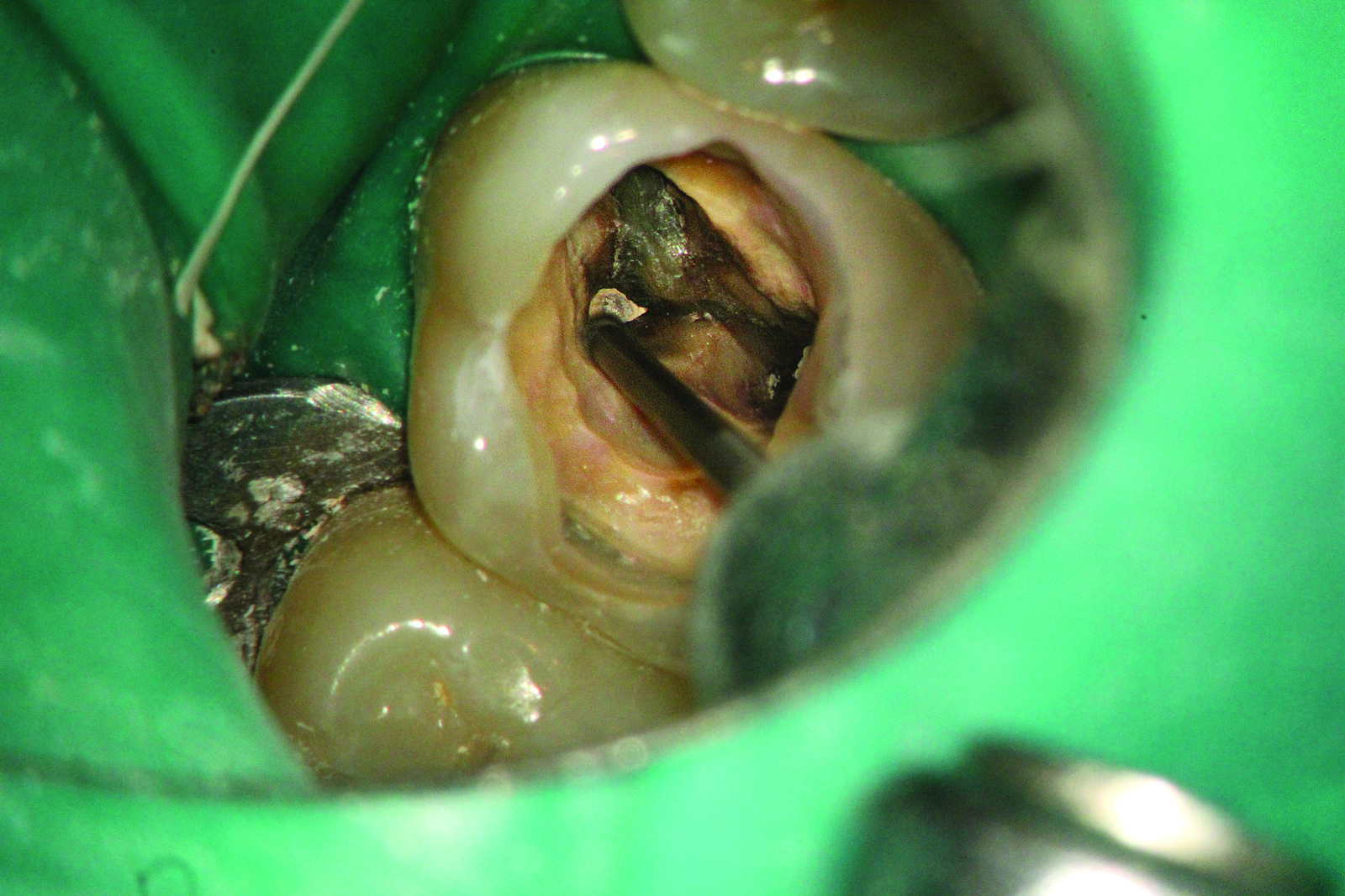
In Figure 8, the typical root canal situation for an upper molar is clearly visible: There are a palatal, a distobuccal and a mesiobuccal canal here. If an imagined vertical connection is drawn from the palatal to the mesiobuccal canal and a line is drawn at 90 degrees to this to the canal, this gives the area in which there is a very high probability of locating the mesio-central canals.
With the assistance of a low-speed Kavo contra-angle handpiece Mastermatic M20 L and a fixed Lentulo spiral, a medicated insert is rotated into the canals during the treatment session. A cotton pellet is then placed onto this medicated paste and a layer of Harvard cement is applied as a ‘provisional’ sub-filling.
The Harvard filling as an obturation over the medicated insert enables the tooth parts placed on top to cauterise, prime and bond, without the medication being rinsed out again.
Another advantage of the Harvard cement is that it can be clearly distinguished from tooth-coloured composite. So when re-entering the cavity at the next treatment session, when repeated disinfection and root filling takes place, access to the canals is visually simplified.
If the composite adhering directly to the pulp chamber floor has to be removed, eg for corrective treatment that may be very difficult and only possible under magnification – because of the similarity to dentine colour – it is helpful as with this patient to remove the composite residue directly adhering to the pulp chamber floor very carefully with a bud burr (Figure 9) running with an air spray.
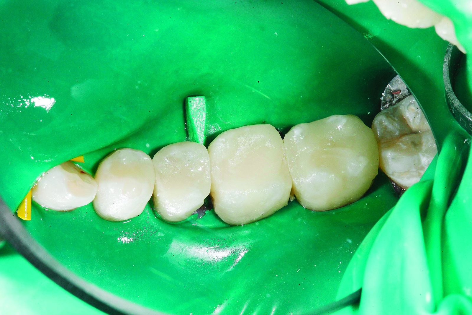
After completion of the entire cauterisation process, the central core of the endodontically prepared tooth has then likewise been coated with a flowable and a definitive composite right to the occlusal surface (Figure 10). After removing the dental dam and critically checking the interdental spaces for dental dam residue, even in the subgingival sections, the occlusal height and the lateral intrusions were checked and ground off with occlusion foil. In Figure 11, the dense, newly coated composite restoration is clearly visible.
The tooth is now completely prepared and very thoroughly disinfected; it should not cause the patient any further difficulties. A further treatment appointment was agreed for around four weeks’ time, in which only the core of the created adhesive restoration was trepanned after thorough drying.

As shown in Figure 12, I prefer the Kavo Turbine with a fixed sharp crown slitter for establishing the coronal access opening. I recommend the following trick to reduce the risk of slipping with the crown slitter or diamond when trepanning a hard zirconium oxide crown: simply use the index finger of the left hand as a supportive guide for the head of the turbine (Figure 13).
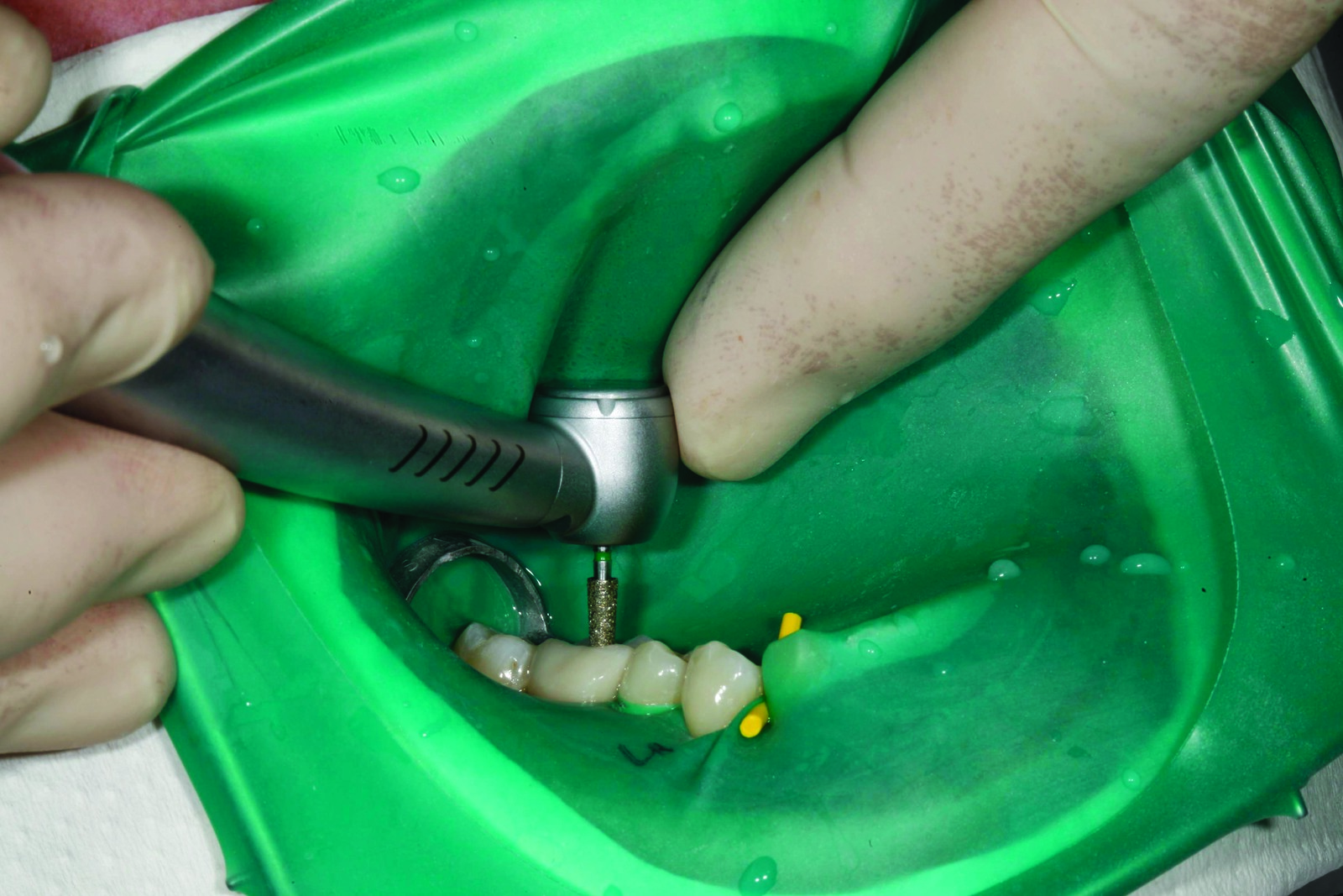
When the occlusal core is drilled to the level of the provisional Harvard sub-filling, I exchange the turbine head for an extra-long, round-end diamond (Figure 14). This removes the lateral overhang of the pulp roof but avoids the floor of the pulp chamber for reasons of perforation prophylaxis.

To completely remove the medicated insert, the canals were well rinsed with sodium hypochlorite. For safety reasons, the rinsing cannula remains unscrewed on the disposable syringe (Figure 15) so that it does not disengage even at high rinsing pressures. During the rinsing process, the assistant suctions away the arising rinsing fluid with the saliva ejector without screw-cap directly on the oral cusps.

During the appointment for thermoplastic root filling, the dental microscope was used again to investigate the entire pulp chamber floor and the prepared root canals critically for any still remaining fine canal structures. To do this, the xenon lighting of the modern dental microscope and up to 24x magnification are of great assistance. If very fine lines/structures are to be carefully filled, under which a further canal is hidden (for example as shown in the patient in Figure 16), a blue Kavo contra-angle handpiece with air spray and a small, extra-long bud burr are recommended. Rhodium-metallised mouth mirrors are ideal for working at high magnification levels, as they come in two sizes (1.5 cm and 2.5 cm) and they can be unscrewed at the handle to be exchanged when they are scratched. The extra-long bud burr remains far enough away from the pulp chamber floor so that the fine structures that are being worked on can be seen in the mirror (Figure 17). Figure 18 shows a very fine mesio-central canal entry, into which the number eight file inserted in a cautious motion.


Clinical cases two and three: pulp denticles and calcified pulp stone
Over the years in dental practice, we have found that it is usually teeth that have a legacy of other treatment that require endodontic work. The historic effects of decay, drilling, fillings, crowns etc have often led to a permanent calcification and sclerosis of the canal structures and the pulp chamber.
These pulp denticles, which fill the entire pulp lumen in a sclerosed form, are a challenge when carrying out treatment with the naked eye or with weak magnification, as they are often identical in colour to the dentine.
A dental microscope with xenon lighting is therefore the first-choice treatment medium for the identification and targeted removal of pulp denticles. In addition, an attempt can be made with methylene blue dye to colour any remaining fine tissue residue that often flows around the centrally calcified pulp stone and so to obtain an indication of the denticles. The pulp denticles are removed very carefully with the assistance of the dental microscope and sharp, extra-long bud burrs – always under the premise that no perforations are made in the bifurcation.
In Figure 19, a pulp denticle of this kind can be seen in tooth LL6 crowned many years previously. The family dentist believed that this was already the floor of the pulp chamber as the search for canal entries was rather more mesial. The X-ray image in Figure 19 shows on the one hand the mesial search direction of the family dentist – and on the other that a perforation would have occurred if searching had continued further in this direction after entry into the mesial canals. Luckily for the patient, searching was stopped and the patient was transferred to me as a specialist in endodontic treatment.
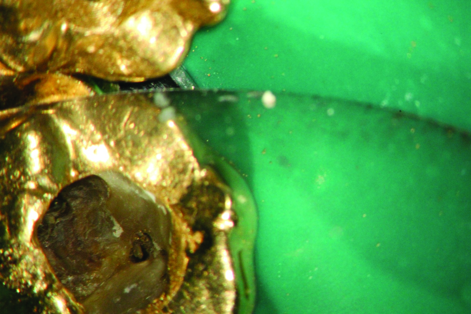
Figure 20 shows the pulp denticle with its browner colouring, which is blocking access to the canals in the central part. With the sharp bud burr, this tissue feels somewhat ‘squashier/softer’ than healthy dentine. The grey tissue visible on the X-ray in the core of the pulp chamber is the pulp denticle. Following successful removal of the denticle, actual preparation and expansion of the canals can be initiated (Figure 21).

A further problem is presented by severely calcified canals, often with canal entries only one hundredth of a millimetre wide. Besides magnification, the use of 30% H202 can help here, which in small quantities via a rinsing cannula is trickled very carefully into the pulp lumen. Excesses are immediately suctioned away coronally by the assistant with the saliva ejector (without screw-cap). The dentist then uses paper points to carefully dab away the H202 remaining at pulp chamber floor level and checks whether any minimal bubbles are arising anywhere. This ‘bubble test’ is a final opportunity to find any remaining canals.

Figures 22-24 show the clinical situation of a crowned tooth LR6, which continued to give the patient trouble despite the root filling from years previously. During corrective treatment and the removal of previous root fillings, there was still a small mesial ridge between the two filled canal entries, under which the third mesial canal was hidden.

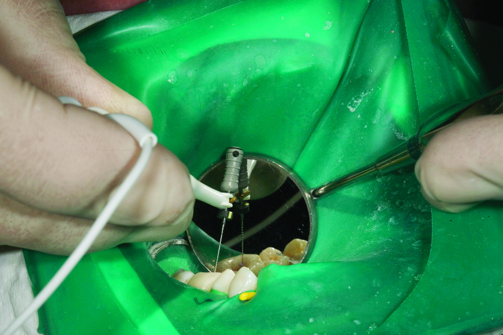
When investigating such fine canal entry structures, electrical methods for length measurement are extremely important. To do this, I clamp a number 10 Kerr file to the handle of the apex locator (Figure 26) and guide the file by the handle towards the canal entry point to be investigated. In this position, it is possible using the large rhodium-metallised mouth mirror to see indirectly what is being touched with the tip of the file. At the same time, the scaling of the apex locator shows very precisely how close to the constriction the file is reaching (Figure 27). When the canal entries have been located with the aid of these tricks and measures, a careful start is made on investigating the traversability of these canals with a number 10 Kerr file attached to the apex locator. This is inserted in a careful rotary movement with minimal up and down (maximum 30 degrees) into the canal and moved towards the apex.
The use of transparent lubricant (eg Smearclear made by Kerr) can be helpful here as it allows visibility at the same time. The stability of the length measurement device must be observed at all times so that any over-instrumentation beyond the constriction is avoided.
After each investigated canal, the file is disinfected in the instrument rack (Figure 28) before it is inserted into the next canal for investigation. The instrumentation sequence is carried out manually from ISO number 10 to number 15, number 20 and then to number 25 Kerr files. Through careful manual instrumentation in the minimally rotating ‘wiggle-wiggle-pull motion’ pictured, the aim is to gain smooth access through the canals precisely to the apical constriction.
Depending on the traversability of the canal entries, a Gates Glidden drill fixed in the blue Kavo handpiece (Figure 29) is then used to establish the coronal flare, which can be used as a reservoir for the disinfection solution and enables simultaneous straightforward insertion of the instruments so that they are not under stress coronally from too narrow a canal entry.
After the use of each file size, the entire canal system is disinfected with sufficient 5% sodium hypochlorite. During the entire preparation procedure, NaOCl remains consistently in the core of the tooth. In particular in the upper molars, there are canal systems that initially demonstrate a connection line, which can then be fostered and enhanced through rotary preparation with the help of ultrasound equipment (eg Sybron Endokit) (Figure 30).

The aim is always to remove all tissue residue and debris from the canal system and to ensure chemo-mechanical disinfection. If the desired preparation width to the constriction has been achieved by hand and the canal system is traversable, mechanical preparation begins after rinsing with sodium hypochlorite.
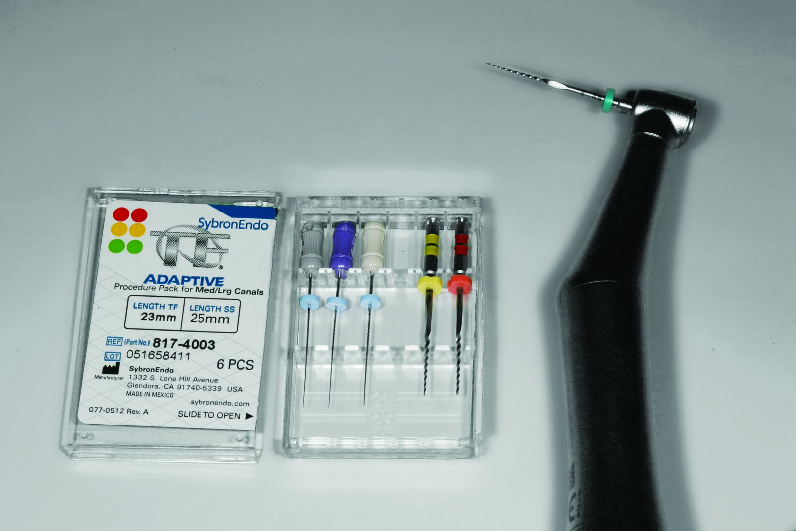
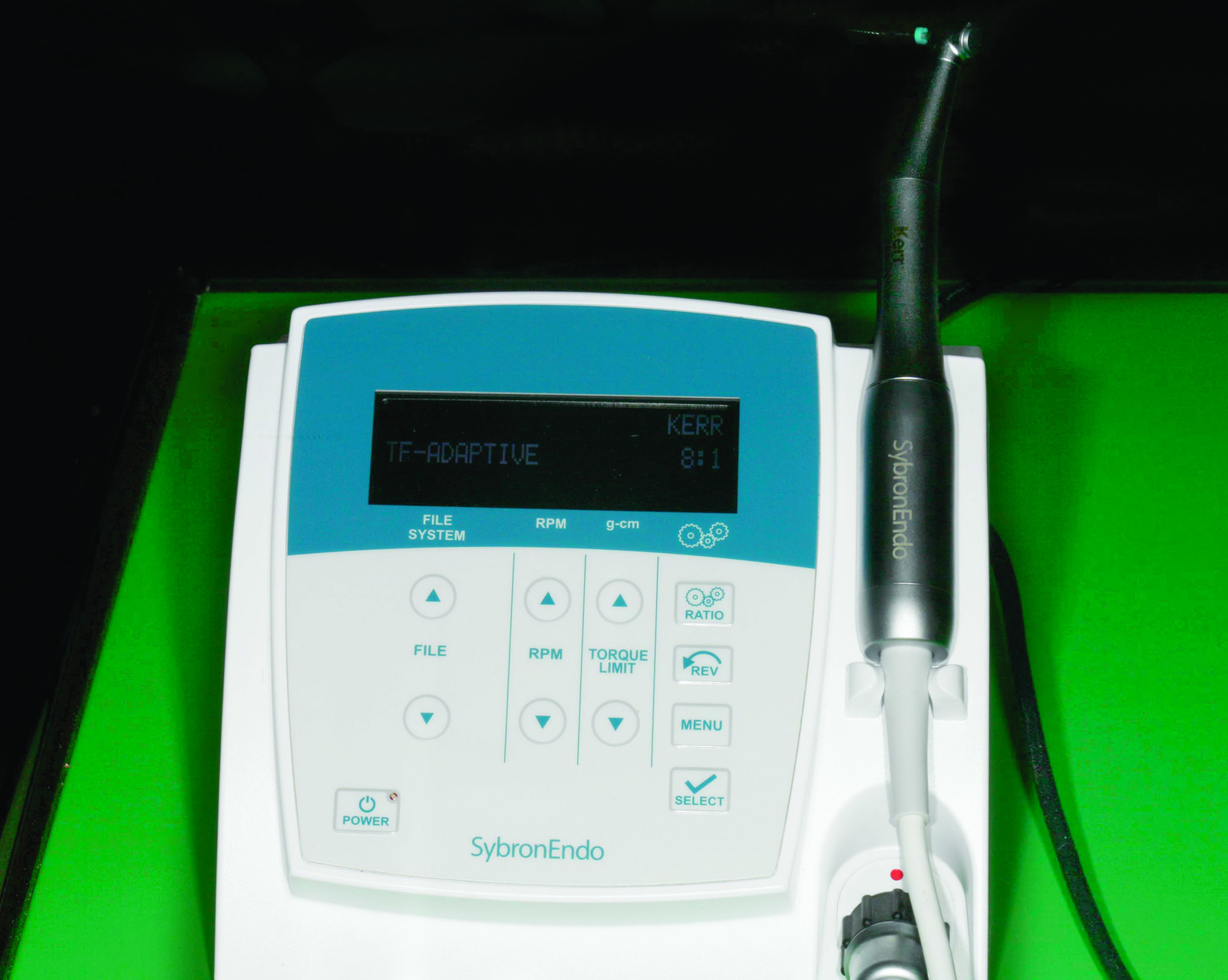
Because of my experience in the treatment of thousands of teeth, I am firmly convinced that this manual preparation of the canals represents the best option to prevent instrument fracture. The TF Adaptive File system from Kerr (Figure 31) works in a rotary motion, as long as the motor (Figure 32) does not encounter any strain. If any strain occurs, the system goes into a reciprocal motion. The work sequence of the TF Adaptive system is therefore always very straightforward. With small canals, canals are entered first with the SM1, then the SM2 and then the SM3 file in a rotary motion (Figure 33).

Thorough rinsing with 5% NaOCl and continuous renewing of the rinsing fluid are important so that the arising debris is constantly rinsed out of the prepared canals.
I usually prefer two appointments for the endodontic treatment of a tooth as we are usually dealing with infected canal systems so a disinfectant, medicated insert over several weeks can only improve the hygiene situation in the canal systems.
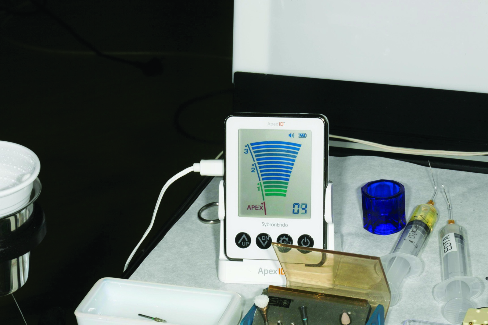
If in the first treatment session, the tooth is completely prepared and at the second appointment is shown by X-ray to be clinically normal, we can move on after repeated and sufficient disinfection to the root filling. To do this, one of the Kerr manual files corresponding to the last preparation width, clamped to the electronic length measurement device of the Sybron Endo Aprex ID, again measures the apical width to the constriction. After this, a calibrated measurement gauge is used to cut the master cones exactly to size so that they correspond precisely to the measured apical width. These master cones are inserted into the canals and their perfect fit is checked using the pincette. A slight resistance should be felt through the clamp in the apical section.

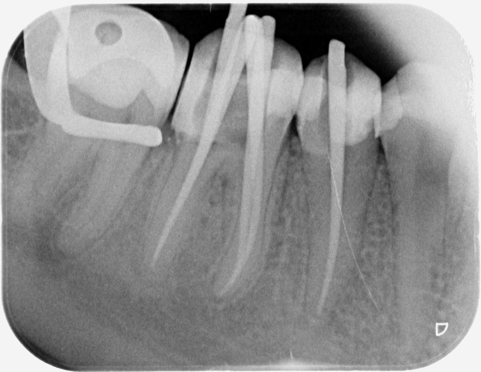
An X-ray is then taken of the master cones (Figure 34) to check the position and fit of the cones. If necessary, further modifications can be made to the width and length of the cones. After the canals have been dried completely with paper points, the first master cone is pulled through the selected sealer (eg Sealapex made by Kerr), which has been mixed on a paper block, and is inserted fully into the constriction. The master cone is removed once again, rotated once more through the sealer and replaced in the cavity.
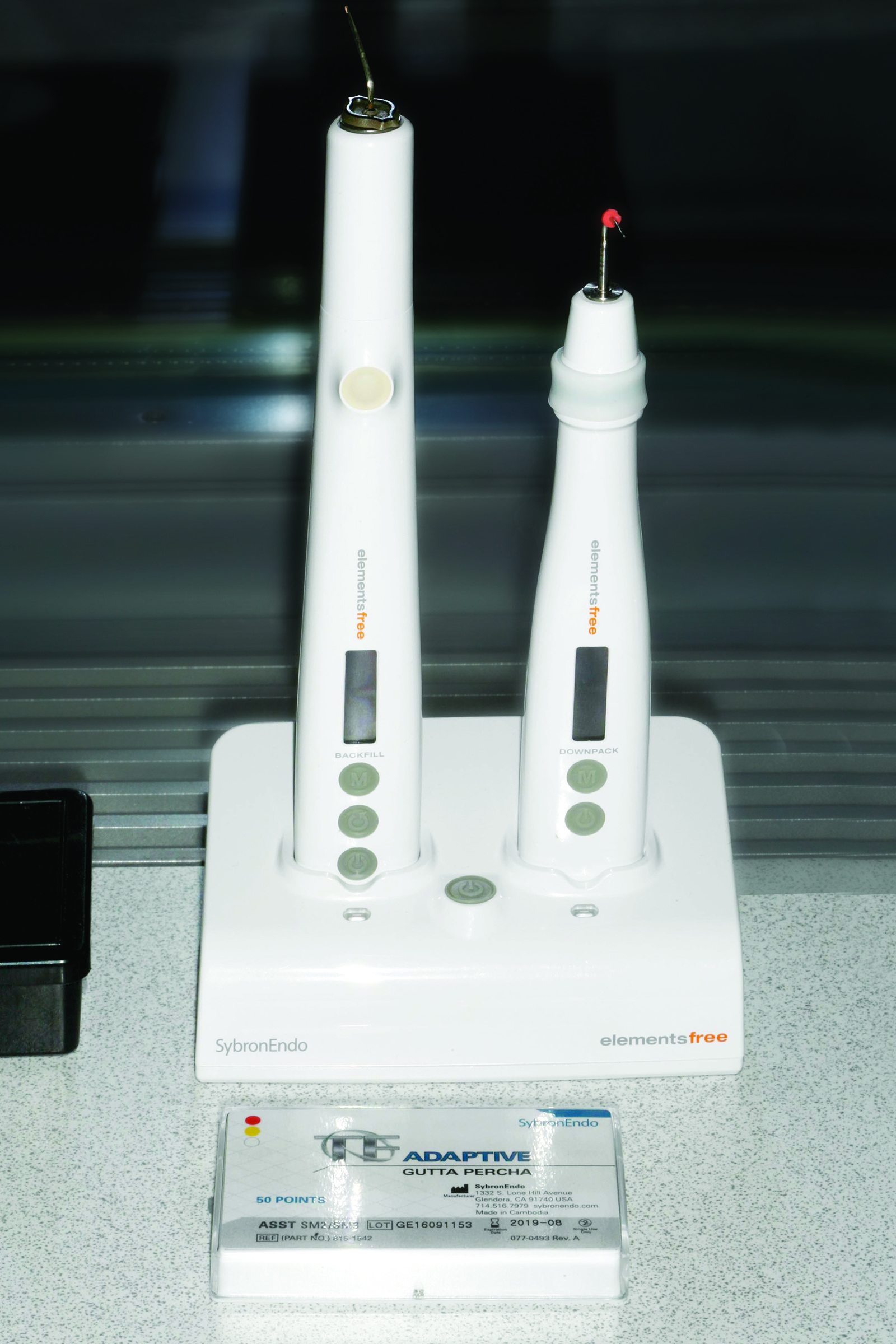
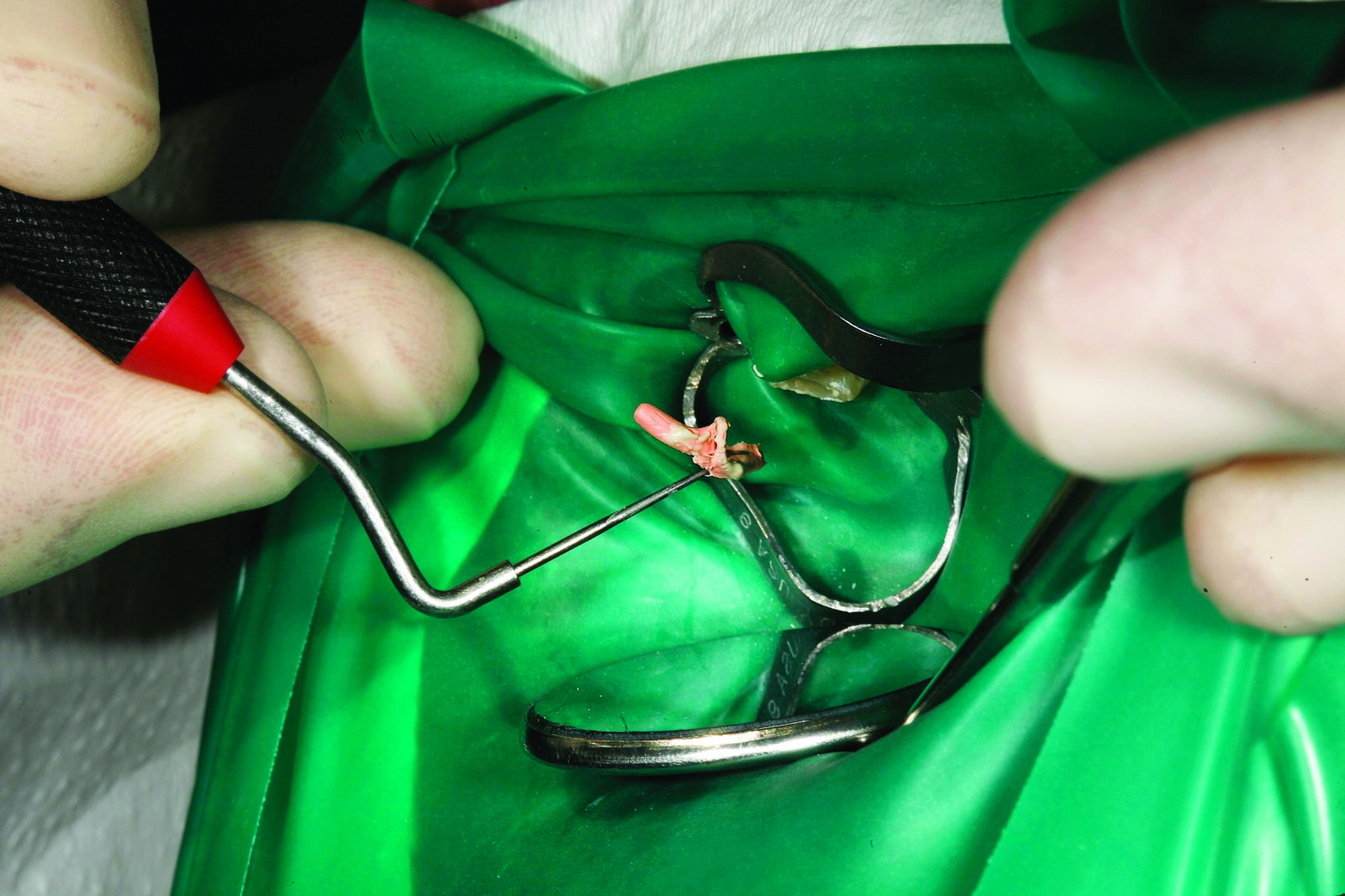
Then, the heat plugger (eg Kerr Elementsfree, Figure 35) inserts the warmed attachment to 4mm before the apical filling point (Figure 36). The heating activation is briefly released so that the cooling master cone gutta percha sets on the cooling plugger attachment; the heat is briefly reactivated so as to extract the coronal section of the melted master cone alongside it (Figure 37). The Buchanan hand plugger is immediately used to condense the apical gutta percha and the setting phase is awaited. Any excess gutta residue that adheres in the coronal lumen of the tooth can be taken out with the Buchanan plugger (Figure 38).
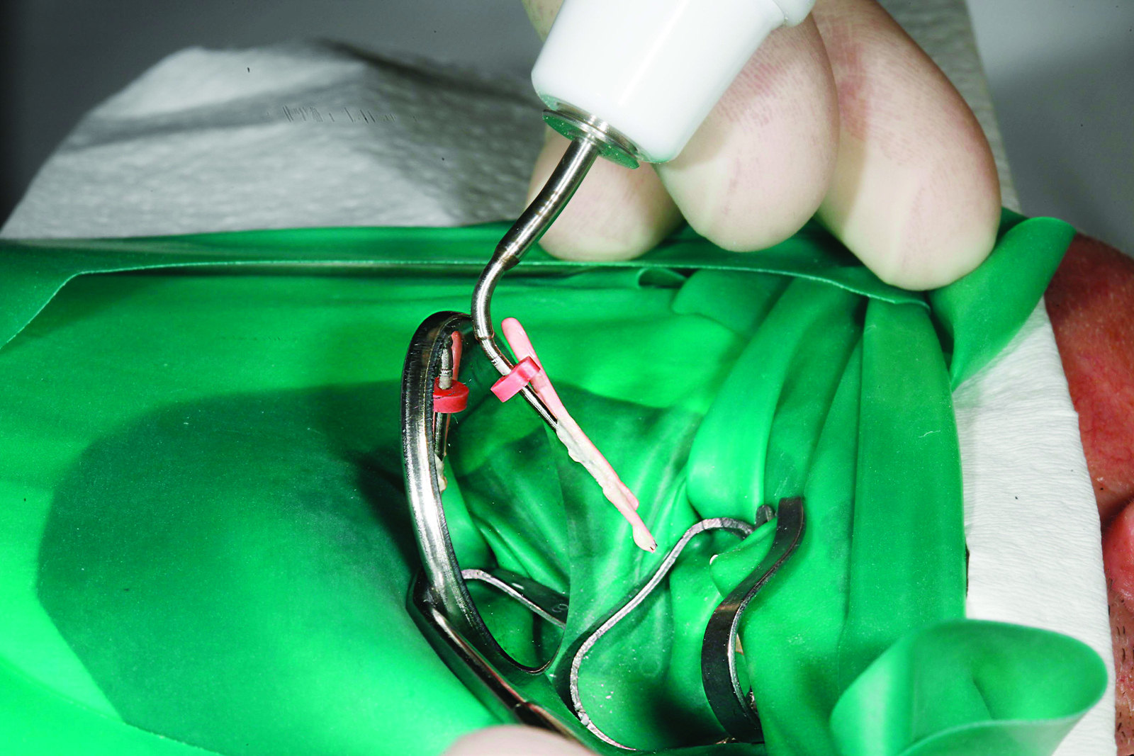
The coronal section of the root filling is then completed with the heating implement. The warmed attachment of the application needle (Figure 39) is placed on the downpack gutta percha for one to two seconds so as to achieve internal coalescing of the downpack with the backfill gutta percha.

The application pistol then moves slowly towards the crown through the warm gutta percha material emerging towards the apex. The root filling ends at the height of the pulp chamber surface. The still-warm gutta percha is immediately re-condensed with the thick end of the Buchanan handheld plugger. The filling of the other canals proceeds in a similar way. Then a final X-ray check is completed (Figure 40).
Clinical case four: endodontic correction
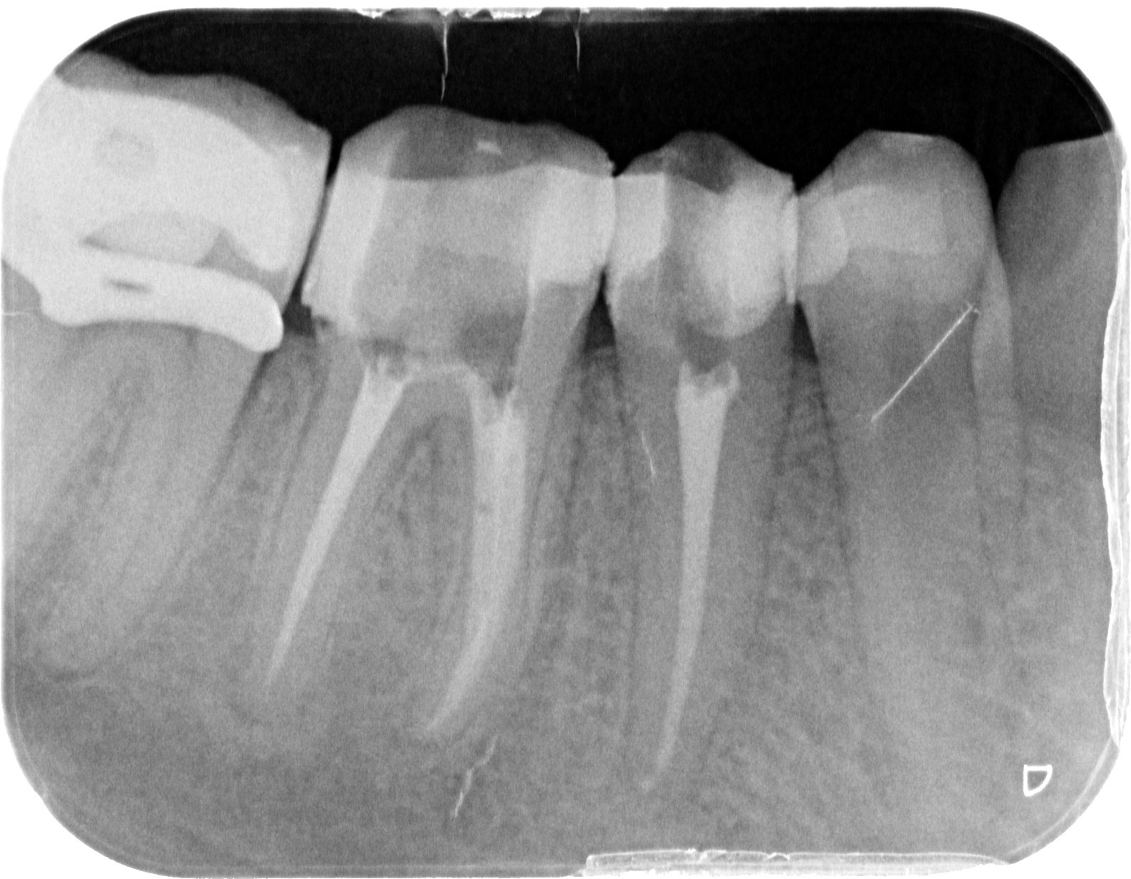
In February 2014, a new patient presented with multiple carious lesions, including tooth LR6, which had already received endodontic treatment but was, like its neighbouring tooth LR5, also showing apical translucency (Figure 41). A conservative and periodontically thorough reconstruction was discussed with the patient as well as the alternative possibility of endodontic corrective treatment of tooth LR6. At an extended treatment appointment lasting four hours, a start was made at the end of February on reconstructing the lower right quadrant. After complete decay removal, teeth LR4, LR5, LR6 and LR7 were built up adhesively with composite in a multi-layer technique. Tooth LR5 first received endodontic treatment and tooth LR6 then received corrective treatment.

Decayed tooth LR8 was extracted. Figure 42 shows tooth LR7, now free of decay, in which the dental dam is held by a butterfly clamp under the cervical defect to enable cleaning and composite build-up. From distal LR7 to LR4, each tooth in turn was freed of decay, disinfected and built up with adhesive. Figure 43 shows the little remainder of tooth LR6 and the macro-mechanical retention drilling holes in addition to the adhesive fixing with primer bonding system.
Before the actual endodontic corrective treatment, tooth LR6 was built up in a thick circle with a layered composite restoration (Figure 44). Only then did the actual endodontic corrective treatment take place. By creating the circular ring of synthetic material, it was possible throughout the corrective treatment to flood the inner lumen with chloroform and so to soften old gutta percha for removal with a mechanically rotating revision file
(eg Kerr K3XF) and to perform coronal suction. If the tooth had been open, the chloroform would have flowed out in all directions, causing the dental dam rubber to dissolve, leading to a contaminated situation.
So as to achieve approximal close-fitting contact points, as shown in the final image of the completely reconstructed quadrants in Figure 45, it is crucial to wedge securely only an approximal edge with a thin matrix and only then, for example, build up the distal cavity area completely to the occlusal centre.
After finishing with a fine diamond-coated steel strip (grain 20-40 micrometres), a thin mesial matrix is densely established and is wedged as much as possible. After coating the mesial composite wall, a smooth interdental finish is achieved with polishing strips and then the neighbouring anterior tooth is likewise built up.
For reasons of comfort and hygiene, the composite-restored, reconstructed teeth should have approximal close-fitting contact points at the end of the treatment session, and this is tested using dental floss. After complete preparation of all canals (LR6 four canals, LR5 one canal), teeth LR5 and LR6 undergoing endodontic preparation were then filled with an insert containing calcium hydroxide and were tightly sealed with adhesive.

The interesting feature of the case is the long period of two years until the patient returned for further treatment of teeth LR5 and LR6. Although technically it can be assumed that the medicated insert loses its full effectiveness after several weeks and the teeth should once again be disinfected, X-rays taken two years later (Figure 46) showed that the apical inflammation had healed. Following repeated disinfection with NaOCl, the canals of both teeth were therefore densely filled using the vertical, thermoplastic condensation technique (Figures 47 and 48). The case in point is a good example of the potential of the human immune system, where the practitioner has carried out stringent chemo-mechanical disinfection in all detectable canals and the tooth has been densely built up with composite in the same treatment session.
Summary
The conservative case studies shown here clearly indicate the potential – even long-term – that are made possible by modern, established adhesive and coating techniques with composite. With the current composite systems, such as Optibond XTR and the nanohybrid universal composite Harmonize from Kerr, a broad spectrum of restorative fabrication of defective anterior and posterior teeth can be achieved.
Current endodontic treatment concepts with mechanical instrumentation (eg with the TF Adaptive System made by Kerr) and systematic chemo-mechanical disinfection offer the possibility of healing even extensive apical defects.
Using the thermoplastic, vertical condensation technique, eg with the Elementsfree obturation system from Kerr, even extremely complex canal systems can be filled permanently, densely and three-dimensionally. Thanks to continuous electromagnetic length measurement with today’s excellent devices, eg Apex ID from Kerr, endodontic treatments can be carried out unerringly and manageably.

