


Follow Dentistry.co.uk on Instagram to keep up with all the latest dental news and trends.
 Luc and Patrick Rutten explore the use of digital workflow and interdisciplinary planning to improve the quality of implant treatment.
Introductory thoughts
CAD/CAM is an acronym for computer-aided-design.
Manufacturing technology is available for dental practices and dental laboratories. This enables clinicians and dental technologists to design implant positions and dental restorations on a computer screen.
The standard treatment approach uses conventional impression techniques and stone casts for the manufacturing of dental restorations. In contrast, computerised engineering technology is related with consistent precision and reproducible results in a streamlined work process.
The traditional handcraft is still a part of our daily workflow but is losing importance rapidly.
The use of digital computer dental technology and the continuous development ensures a systematic growth into the mainstream and its users.
Additionally, continuous innovations in the computer technology and dental processing ensures new opportunities in the field of prosthodontics, implant dentistry and dental technology.
The establishment of CAD/CAM technology has been a game changer for the production of crowns, bridges, abutments and implant supported restorations. They are produced using on-screen designing with software applications with the opportunity to choose different dental materials within the system.
The system can be used in a laboratory setting or in a production centre.
This article discusses new procedures to integrate individual patient data into the digital workflow, and interdisciplinary team approach between the different treatment partners to reach one goal: to improve the quality of treatment and the final outcome.
Goal
One of the challenges in restoring anterior teeth with implant restorations is maintaining the natural looking of the peri-implant area and creating a natural looking dental restoration.
The goal is to describe the workflow chronologically to optimise the implantological and prosthetic result.
This improves the efficiency of the surgical procedure and rendering the restorative outcome more predictable in terms of biology, function and aesthetics.
Case presentation
A middle-aged female patient has worn old composite build ups for many years which are aesthetically very unsatisfying (Figures 1-2).
All of the maxillary incisors are seriously periodontally compromised.
The prognosis in the long-term is negative and makes extraction the best option.
Teeth 12 and 13 have been extracted first (Figure 3) and a removable prosthesis has been manufactured (Figure 4).
The goal of surgery treatment will be a guided implant placement and immediate implant supported provisionalisation in the aesthetic zone.
 Figure 1: Preoperative view of the removable prosthesis
Prosthetic planning
Harmonising a beautiful smile requires a perfect integration.
The goal of an aesthetic makeover is to develop a planning treatment achieving a successful and functional result that requires an understanding of the interrelationship among supporting oral structures, occlusion and soft tissues (Figure 5).
This is the kind of information we receive from the clinician on beforehand to get a detailed inside of the final outcome.
This credit goes to professor Amelie Mainjot who prepares all the cases in this detailed way.
Natural dentition provides an unlimited library of possible tooth designs and teeth positions. The use of digital scanners allows to create our own library of tooth design in shape and position.
The arch of an 10S can be segmented into individual STL files of each tooth using different tools (Figure 6-7).
Creating a virtual tooth set up
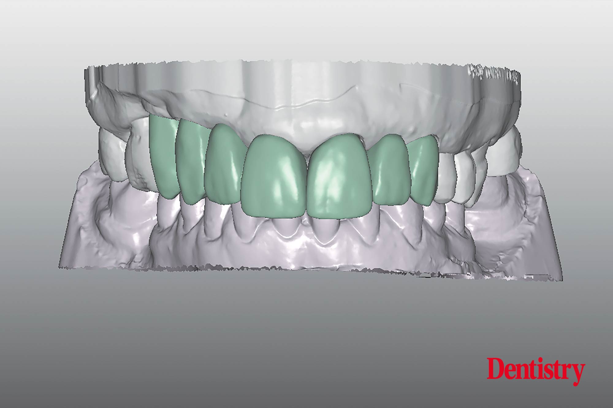
The STL files of the initial situation after the first extraction (Figure 8) were imported to the software. A virtual set up has been created what allows to judge the position and volume of the temporaries.
This on-screen set up is created in a natural ideal shape of the incisors (Figure 9-10-11). The setup has been made in a more or less perfect cervical outcome and with a correct tooth axis according the prosthetic planning. It should show a certain symmetry of the two centrals at the gingiva level.
The setup has an average length of 10-11 mm.
The height of the apical gingiva margins of the anterior teeth determining the ideal contour for this region.
Connecting the zenith of the two central incisors to the zenith of the canines, the zenith of the laterals should be 1mm below this connection line.
 Figure 5: Detailed prosthesis planning and soft tissue corrections
Virtual implant planning, surgical guide – a shift of paradigms
Guided dental implant surgery is when the clinician utilises advanced software and imaging technology to place the implants more efficiently, precisely and accurately.
The technology used in computer guided implant surgery include: 3D imaging, CBCT scans (C one Beam Computed Tomography), CAD/CAM computer imaging and digital X-ray.
Digital treatment planning is a virtual placement of implants that allows to identify and fully use available bone volume to optimise implant placement. This is completed according to the approved prosthetic design to relate the restoration with the patient’s soft and hard tissues from prosthetic and surgical perspectives.
After the virtual design has been finished, the clinician can make the planification for the implants (Figures 12-13).
This digital technology predetermine the precise 3D position of the implants, and to transfer the planning information into the surgical templates.
The surgical template is a complete and sophisticated system for prosthetic driven solutions and guided implant surgery.
Once the surgical template has been delivered at the practice the clinician can install the implants.
The software of the implant system offers guided pilot drilling and fully guided implant placement (Figure 14-15).
The position of the inserted implants is predictable (Figure 16-17) according the digital planning.
Directly after implant placement an IOS has been taken to provide the patient with a PMMA CAD/CAM scanned screw retained provisional (Figure 18).
In the meantime to bridge the period of manufacturing the CAD/CAM milled temporary bridge a removable prosthesis has been placed (Figure 19).
 Figure 12
Uploading STL files and 3D printed models
The STL has been uploaded (Figure 20) and in the software transformed to allow the 3D printing (Figure 21-22).
Over the past decade the dental industry has been revolutionised by 3D printing technology. Dental 3D printers need to be very accurate, fast reliable and flexible.
Resin 3D printers (stereolithography) are highly popular as they produce higher quality 3D prints.
The printed model has pre-made holes for the analogue and a locking mechanism on the bottom interior of the hole (Figures 23-24-25).
Once the analogues are connected the model will be reshaped at the height of 12 and 22 with a metal bur and re-modeled to a natural sulcus – ovate pontic (Figure 26).
For the manufacturing of the temporary screw retained bridge the 3D printed model has been scanned and prepared for on-screen designing (Figure 27-28).
The teeth will be picked up out of the library and can be set up with the opportunity to place these in the right position and shape with the possibility to adapt to the desired situation.
Concerning relationship of and between front teeth, results of many studies have been shown that the width of the central incisors is around 80%-85% of their length (Figure 29). Patients consider these dimensions and proportions to be optimal.
 Figure 20: Uploading the STL file ready to transform into the soft-ware
CAD/CAM provisional
The manufacturing of the CAD-CAM customised provisional screw retained PMMA bridge start now.
The shape sub-gingivally of the bridge should be concave from the top of the implant to the gingiva level.
After the sulcus of the 3D printed mastercast has been shaped ideally, the manufacturing of the customised PMMA bridge can begin.
The temporary titanium interface will result in a titanium-titanium connection into the implant (Figure 30).
The interface is designed for a precise fit between temporary bridge and implant and offers us high mechanical strength.
Next, titanium cylinders will be bonded into the PMMA CAD/CAM milled bridge.
Shape and position of the provisionals must be done according to the shape and the position of the final restoration. They will be manufactured after osseointegration of the implants and complete healing of the soft tissue (Figure 31-32).
An understanding of the biological aspect of the soft tissue is very important in this stage.
The shape of the sub-gingival design can be discussed on before-hand according the instructions of the clinician in order to avoid later problems.
An ideal shape allows healing of the soft tissue to maturate a good contour and will maintain the soft tissue architecture. This requires a close collaboration between clinician and lab technician.
Gingiva protection
One of the most important issues with temporaries is that the part of the PMMA which is in contact with the gingiva should be polished manually as smooth as possible to avoid plaque accumulation.
Figures 33-34 show the provisional screw retained implant bridge in the patient’s mouth.
After healing of a modified connective tissue graft, the tissue bed can be prepared for ovate panties.
The pontics (12 and 22) may appear to be too long since the pantie is seated 1 to 1.5 mm into the gingiva, this ensures sufficient support.
Ultimately the panties seemed to virtually grow out of the gingiva. The panties emergence profile was not much different from that of a natural situation (Figure 35).
 Figure 30: The provisional titanium cylinders are screwed on top of the replica's
Scanning procedure of zirconia screw retained bridge and design
After healing of the soft tissue, the arcade-shaped contour and the pseudo-papillaes are clearly visible (Figures 36-37-38-39). They are the fruits of the periodontists utmost work (professor France Lambert).
Approximately six months after osseointegration and maturation of the gingiva the IOS can be taken in order to move to the next step of manufacturing a definitive restoration (Figures 40-41).
IOS (intraoral scanner) is one of the most exciting new technologies in dentistry. It was developed for clinicians to create a digital impression of the tooth’s anatomy and implant positions and produce accurate images which can be judged on the computer screen.
Digital impressions offer patients the convenience of not having an unpleasant feeling. It simplifies clinical procedures for the clinician and allowing a better communication with the dental technician. It replaces the conventional impression techniques.
The next step is to upload the STL files and to transform these with the software to allow the printing of the 3D models (Figures 42-43-44). The 3D printed models will be prepared for scanning.
The analogues (Figure 45) will be installed in the 3D printed model. The printed model has remade holes for the analogue and a locking mechanism on the bottom interior of the hole (Figure 46).
It is a secure press-fit and one insertion position which is always correct and automatically centred. The specific tools for all platforms are used to pull down the analogues into their correct position (Figure 47-48).
 Figure 36: The nicely healed soft tissue
The printed 3D model
The definitive 3D printed model with removable soft tissue (Figure 49) will be carved by a rounded bur. This is to create an ideal egg-shaped space for the ovate pontics and to become a sufficient support for the soft tissue. Additionally, this will bring it a lot closer to a successful restoration (Figure 50).
The on-screen designing of the soft-ware allows the design and position of the screw retained implant bridge (Figures 51-52).
To avoid chipping and losing translucency, the implant bridge will be manufactured in a semi translucent zirconia.
The labial/buccal part of the bridge will be individually veneered with ceramics.
Also, the palatal side will be full zirconia (Figures 53-54) to ensure a better stability and to avoid porcelain chipping, especially for the canine guidance.
The implant bridge has been manufactured in two parts left and right foreseen with screw access holes (Figure 55).
As well as the occlusal surfaces, the palatal side is produced in full zirconia according planning and anatomical design and function. This allows to design sufficient thickness regarding the connections and to avoid chipping (Figures 56-57).
In order to create a more lifelike aesthetic restoration the labial surfaces are designed to apply different porcelain powders in different layers (Figure 58).
 Figure 49: The 3D printed model is foreseen with a removable flexible gingiva mask

