Diyari Abdah explains how the X-Mind Trium 3D CBCT scanner has helped his practice.
There is mounting evidence in the literature in regards to the diagnostic superiority of 3D imaging versus 2D. As a result, many clinicians today are using 3D imaging either by referring their patients to a CBCT-scanning centre or having mobile units visiting them, and the only benefit of this method is that there is no initial capital outlay to buy the machine.
In contrast, the benefits of having your own in-house CBCT machine are many, including the total convenience of an on-demand service at any time (pre-op or during and after if needed), learning one software and fully utilising it rather than having to learn different software for different machines (manufacturers), thus not utilising it to its fully intended use. Additionally, patient appreciation that they do not have to travel to another location and the fact that you care enough to have a machine installed in your clinic for their convenience and yours.
Our X-Mind Trium CBCT unit from Acteon is rather young in our practice, and we have yet to fully utilise it. Every day we find new uses and ways to benefit our patients by using 3D imaging where applicable.
Following the latest evidence from experts in the utilisation of 3D imaging can help a lot in deciding where and when to use it, consequently minimising dosage and improving diagnostics and planning.
We owe our patients the lowest possible dose with the corresponding acceptable diagnostic value, and sometimes a 2D image is just not enough to give satisfactory diagnostic value. A lot of guesswork is often involved with 2D imaging that could affect our decision-making and treatment planning.
Judging every case individually is important in order for the benefits of using a CBCT scan to outweigh the potential risks involved with the use of any type of X-ray unit. A modern CBCT machine should allow for different fields of view (FoV) to be utilised, in order to minimise the dose to the patient.
Despite the choice of four different FOV settings on the X-Mind Trium, and other settings that reduce the radiation significantly, individual assessment of every case is still very important to get the most of the 3D image without exposing the patient to extra radiation.
In many cases, a small FoV that is enough for one to several teeth could be equal to a few periapical radiographs but with a much higher diagnostic value.
In order to show how a CBCT scanning machine can affect the day-to-day dentistry in a small family practice, it would be beneficial to share a week’s diary, bearing in mind each practice’s needs are different, but one thing should be common above all, and that is to assess every case individually and never take 3D scans routinely, even despite their clear benefits.
When a 3D image is necessary, patients appreciate the information and education they get by discussing the case with them while pointing to vital structures and solutions in 3D versus an old fashioned 2D image that did not make sense to the untrained eye in most cases.
So here are a small selection from a week’s diary utilising the X-Mind Trium 3D CBCT scan in the clinic. More CBCT scans were probably obtained on any one day depending on the cases on that day, however, due to space limitations in this article, only one to two cases per day were selected.
Day one
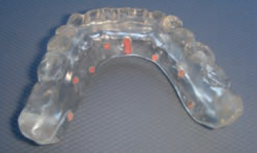
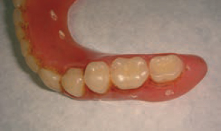
The patient had all his lower teeth extracted many months ago, due to mobility and infections and preferred to have a fixed solution through implant therapy. Patient currently is wearing a well-fitted temporary lower denture. Initially the idea was to take a scan of the existing denture with radiopaque markers (gutta-percha in six to eight holes made in the denture) to plan for the placement stage. However, a decision was made to duplicate the existing denture using a Lang duplication flask in order to fabricate a clear acrylic radiographic guide (Figures 1 and 2).
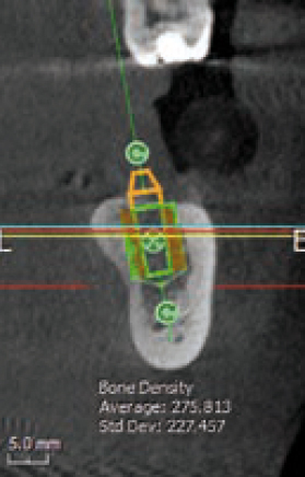
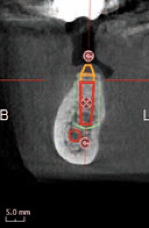
A 3D scan was obtained using the X-Mind Trium 3D CBCT scanner to be utilised as an invaluable resource in the treatment planning of the case. Through the scan, the type and position of the implants in relation to the density of the surrounding bone were checked.
The AIS 3D software that comes with the device, includes a library of most current implants on the market, allowing to place the right implant in the right angulation plus abutments and crowns in order to maximise the predictability of positioning the implants, thus improving its success.
For clinicians who use more than one implant system, to change the implant model that was inserted from the library, we simply click in the middle of the implant and the implant library is opened again and it is possible to choose another implant model, the software will keep the same insertion point and direction of the previous one.
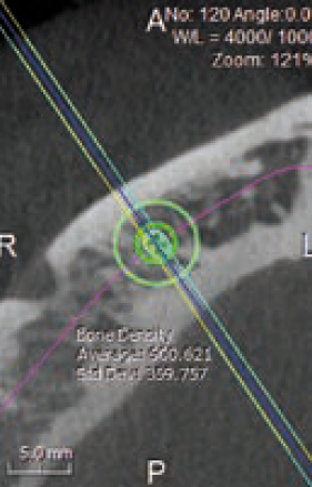
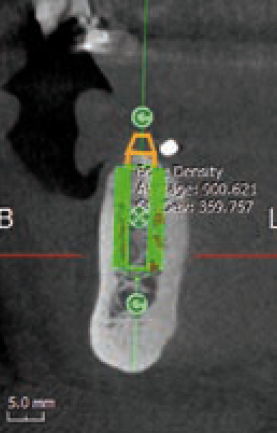
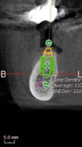
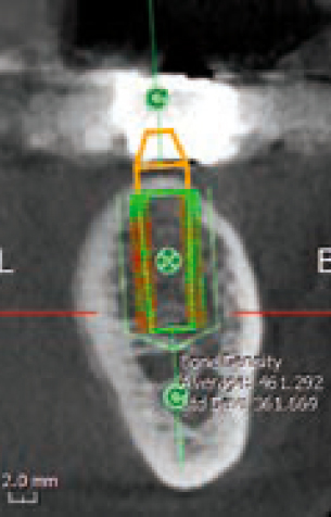
In addition, the software will easily evaluate the bone density around the implant. The aim is to show, both through colour maps and numerically (Figures 3 and 4) the values before commencing surgery (green if the values are acceptable and high and red if the values are low – Figure 5), allowing the clinician to make the right decision. This can also be a very good educational tool to show patients how their bone density potentially is around the implants.
In our experience, patients like this feature once shown what they mean.
Day two
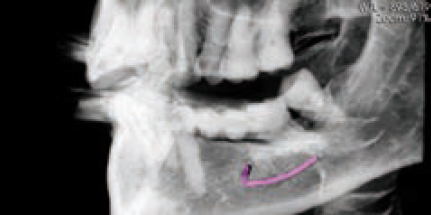
An implant is planned to replace a missing lower molar, and the position of the mandibular canal is not very clear on a 2D image anyway, and even on the 3D image the position is still a little confusing. Here we decided to use the AIS software’s Flymode option, which is like a virtual endoscope that follows the mandibular canal tract from within, and aids to clarify the path and double check if our nerve tracking was correct (Figure 6).
This is one of the unique features of the software that can help clarifying and control nerve-tracking.
Day three
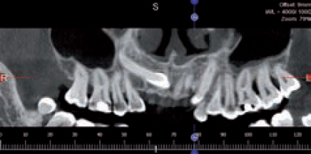
Obtaining the correct position and trajectory of a retained upper canine has been traditionally dealt with by taking different 2D images (periapicals) at different angles and possibly an occlusal film to determine the correct position in the bucco-palatal aspect together with some guessing work.
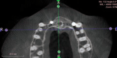
Three dimensional imaging can be an invaluable tool for this matter. The patient refused orthodontic extrusion of the upper left canine and wanted both the deciduous and permanent canines extracted in order to be replaced by an implant-supported crown. In planning the case, a CBCT scan was obtained to serve many purposes as to assessing the positions including any anatomy and bone surrounding these teeth. Since this image was taken, both teeth were extracted and the socket was grafted fully to prepare the site for a later placement (Figures 7 and 8).
Day four
Case one
A lower molar case was in the planning stage, and the position of the mandibular canal was located.
At this stage, different implant sizes were tested to check for best fit and maximum integration prognosis in the future.
The AIS software indicated that the first implant was too long and there was a risk of nerve damage (Figure 9), thus another implant size was chosen to allow sufficient clearance above the nerve and the density of the bone was chosen at the same time, indicating good ‘green’ values that the patient also could understand (Figure 10).
These tools as mentioned above can be quite an eye opener for patients and their engagement can effect the outcome positively.
Case two
A broken and loose bridge was planned to be re-moved. The lower left second molar, which served as the most posterior bridge abutment tooth, was beyond saving (visual inspection and probing).
Three dimensional imaging helped with planning the case. It helped tracking the position of the mandibular canal in relation to the proposed implants (Figures 11 and 12).
In addition, the density of the bone was also checked (Figure 13), indicating that a wider implant possibly is a better choice to improve integration rather than the current one used from the implant library. This will also allow us for deciding to perhaps perform an under preparation of the osteotomy site in order for the implant to engage in the bone better, this obviously depends on the type of implant used and other factors that the expert clinician will be familiar with.
Day five
This case was performed by another clinician who was hoping to achieve good integration after placing two anterior implants with grafting material.
According to the colleague, primary stability was good at the time of placement and the implants were ‘buried’ in the bone with some buccal fenestrations, hence the grafting. So everything indicated success.
After the patient complaining about some threads showing through the soft tissue, the colleague suggested further grafting to ‘secure’ the implants.
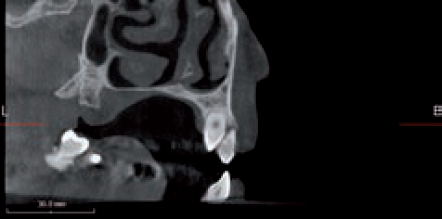
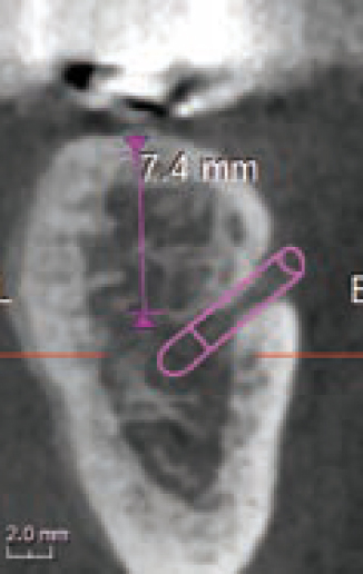
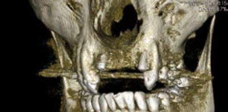
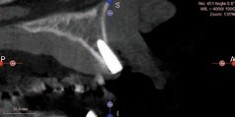
A CBCT scan was obtained (Figure 14) as part of case planning, and clearly the scan shows that this may prove difficult or at least very challenging. In addition, on the 3D image we noted that the tip of the implant on the left side might be colliding with the root of the adjacent tooth, with long-term uncertainty as a result (Figure 15). In this scanning slice (Figure 16) we also noted the challenge ahead for grafting this implant successfully, which indicated that a lot of consideration has to be given and careful planning has to be employed in order to make the case successful.
However and despite the outcome so far with these two implants, the patient appreciated the high value of the 3D technology and being able to see the problem clearly and from different perspectives, eliminating any guesswork that might affect the final outcome, and guiding the treatment in the right direction.
Conclusion
These cases and many more every week pass through any dental clinic, with patients hoping for best available treatment under best circumstances (clinical, timescale, financial etc).
We know that 3D imaging is here to stay and in order to make treatments safer and more predictable for our patients, we have to engage in these technologies and involve the patients more in showing them their clinical conditions and perhaps the limitations (anatomical, structural etc) together with other factors that may affect treatment planning and outcome, hopefully for the better.
We hope to be able to use our CBCT scan for more indications, especially in endodontics as few times we have seen amazingly positive results in using a CBCT scan in some difficult endodontic cases since we acquired this 3D technology. It is the way forward and we wish we had the X-Mind Trium 3D Scanner earlier.
Further reading
Farman GA and Scarfe WC (2009) The basics of maxillofacial cone beam computed tomography. Semin Orthod 15: 2-13
Harris D, Horner K, Grondahl K, Jacobs R, Helmrot E, Benic GI, Bornstein MM, Dawood A, Quirynen M (2012) E.A.O Guidelines for the use of diagnostic imaging in implant dentistry 2011. A consensus workshop organized by the European Association for Osseo-integration at the Medical University of Warsaw. Clin Oral Implants Res 23: 1243-53
Holroyd JR and Gulson AD (2009) The radiation protection implicatios of the use of cone beam computed tomography (CBCT) in Dentistry – What you need to know. SEDENTEXCT
Hultin M, Svensson KG and Trulsson M (2012) Clinical advantages of computer-guided implant placement: A systematic review. Clin Oral Implants Res 23(Suppl 6): 124-35
Ludlow JB, Laster WS, See M, Bailey LJ and Hershey HG (2007) Accuracy of measurements of mandibular anatomy in cone-beam computed images. Oral Surg Oral Med Oral Pathol Oral Radiol Endod 103: 534-42

